GNS3 Lab: VRF Instances and Policy-Based Routing
Virtual Routing and Forward (VRF)
It is a technology that creates separate virtual routers on a physical router. Router interfaces, routing tables, and forwarding tables are completely isolated between VRFs, preventing traffic from one VRF from forwarding into another VRF.
Router's in VRF maintains a separate routing table; it's possible to allow for overlapping IP address ranges. VRF creates segmentation between network interfaces, network subinterfaces, IP addresses, and routing tables. Configuring VRF on a router ensures that the paths are isolated, network security is increased, and encrypting traffic on the network is not needed to maintain privacy between VRF instances.

VRF Instance
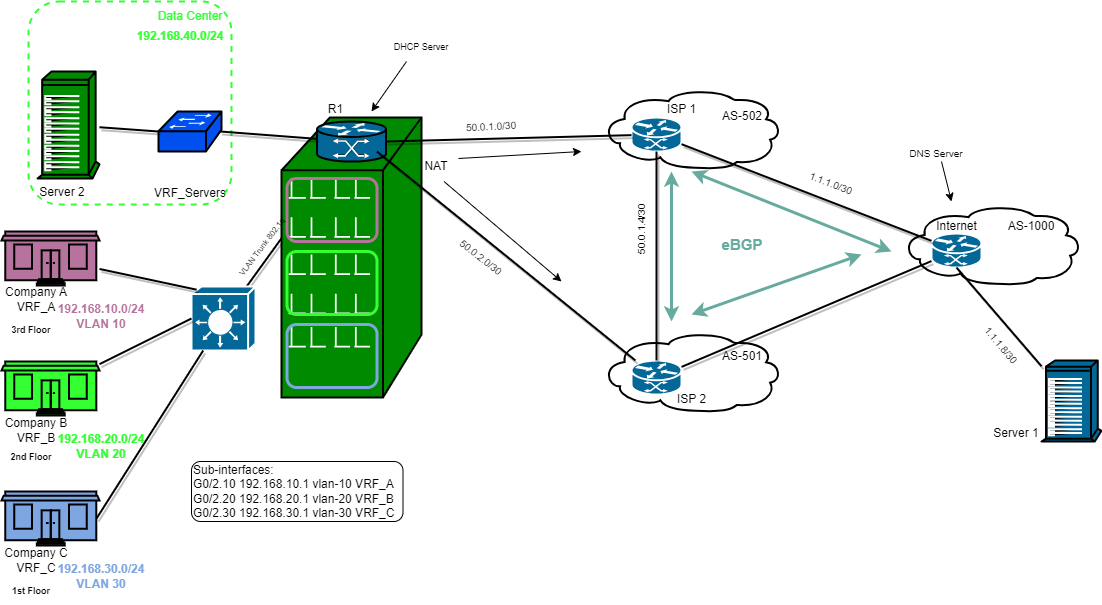
For the Lab, there are Three Companys (A, B, C), and the Data Center for the building which is part of the services being offered to the 3 companies.
Each company's internet and local traffic is logically separated using VRF since there is physically one router (R1) in the building.
For this lab 3 VRF instances were created:
- IP vrf VRF_A
- IP vrf VRF_B
- IP vrf VRF_C
Configured 3 Subinterfaces to be assigned the VRFs and IP address to the Subinterfaces:
- g0/2.10-> VRF_A 192.168.10.1
- g0/2.20-> VRF_B 192.168.20.1
- g0/2.30-> VRF_C 192.168.30.1
DHCP servers for VRF instances
R1 has been configured as DHCP Servers for the VRFs instances:
- ip dhcp pool VRF_A
- ip dhcp pool VRF_B
- ip dhcp pool VRF_C
SW1 Switch has VLANs for each of the companies, Trunk to R1, Access Port connected to each companies network.


After setting up the DHCP Server for the VRF instances. Each company gets its IP address via DHCP and they are connected to their respective default gateways.

Route-Map
For the lab there are 2 ISPs when configuring NAT on the router you can't have several NAT overload statements, because when you apply a second statement, it will replace the first statement leaving you with one NAT statement. So to configure multiple NAT links Route-Map will be used.
Route maps work the same as ACLs, but they also provide additional capability through the addition or modification of network attributes. Route maps allow you to check for certain match conditions and (optionally) set a value. Route maps are critical to BGP because they are the main component in modifying a unique routing policy on a neighbor-by-neighbor basis.
A route map has four components:
- Sequence number: Dictates the processing order of the route map.
- Conditional matching criteria: Identifies prefix characteristics (network, BGP path attribute, next hop, and so on) for a specific sequence
- Processing action: Permits or denies the prefix.
- Optional action: Allows for manipulations, depending on how the route map is referenced on the router. Actions can include modification, addition, or removal of route characteristics.
For the lab standard ACLs are created to identify subnets of VRF (192.168.10.0, 192.168.20.0, 192.168.30.0) that are going to be translated.
Using route-map match subnet of each VRF to NAT outside interfaces the connections from R1 going to ISP1 and ISP2.
- VRF_A Subnet to match interfaces ISP1 and ISP2
- VRF_B Subnet to match interfaces ISP1 and ISP2
- VRF_C Subnet to match interfaces ISP1 and ISP2
After creating the route-map statements. A NAT overload statement is created for three VRFs, to enable translations for the three subnets.
To be able to ping google.com for each VRFs (which is the loopback address 100 for Internet Router from the lab) 66.249.64.19
A default route out of the global routing table needs to be added to each VRF routing table. A prefix-list is created then it is matched in route-map.
Then use route-map with route-replication command.
R1(config)#
ip prefix-list DF_ROUTE seq 5 permit 0.0.0.0/0
!
route-map RM_DF_ROUTE permit 10
match ip address prefix-list DF_ROUTE
Route-replication command:
ip vrf VRF_A
route-replicate from vrf global unicast static route-map RM_DF_ROUTE
!

After adding the default route on each VRF they are able to ping google.com (66.249.64.19) loopback address 100 for the Internet Router


For customers (Company A, B, and C) to access the Data Center route 192.168.40.0 from VRF_SERVERS needs to be added to each company VRF, using route-map and prefix-list.
R1(config)#
ip prefix-list VRF_SERVER_NETWORK seq 5 permit 192.168.40.0/24
!
route-map RM_VRF_SERVERS permit 10
match ip address prefix-list VRF_SERVER_NETWORK
!
ip vrf VRF_A, VRF_B and VRF_C
route-replicate from vrf VRF_SERVERS unicast connected route-map RM_VRF_SERVERS
!

Policy Based Routing
The Policy-Based Routing feature is a process whereby a device puts packets through a route map before routing the packets. The route map determines which packets are routed next to which device. Policy-based routing is a more flexible mechanism for routing packets than destination routing.
Normal routing is only concerned about destination-based forwarding, while PBR gives you more control.
You can use PBR to:
- Direct traffic downlinks are reserved for specific types of traffic or levels of priority.
- Direct traffic is based on the source, not the destination, to steer specific customer traffic down links that match their service level agreement.
- Direct traffic into specific, multi-protocol label-switching traffic engineering (MPLS TE) tunnels, specifically when you use it in conjunction with MPLS TE.
- Choose how much bandwidth to provide specific applications.
- Create fallback links for your most important traffic, so that if the primary link has an outage, you can maintain continuity.
- Choose which traffic gets deep packet inspection, such as for certain, business-critical apps.
- Stratify traffic, giving priority to some instead of others, particularly to satisfy the requirements of an SLA.
- Single out the traffic of certain applications for wide area network (WAN) optimization.
For the lab Policy Based Routing will be configured for VRF A, B, and C. Policy will be the same for all subnets.
HTTP, HTTPS, and DNS for both protocols TCP and UDP originating from VRFs' subnets have to be routed over the path to ISP1, the rest of the traffic goes over the path to ISP2.
- ISP1 routed traffic from VRFs: HTTP, HTTPS, and DNS.
- ISP2 routed traffic from VRFs: others.

An ACL statement is created to define traffic for PBR for each VRFs.
R1(config)#ip access-list extended [VRF_A_ALL_TRAFFIC], [VRF_B_ALL_TRAFFIC], [VRF_C_ALL_TRAFFIC]
permit ip 192.168.10.0 0.0.0.255 any
ip access-list extended VRF_A_POLICY
permit tcp 192.168.10.0 0.0.0.255 any eq www
permit tcp 192.168.10.0 0.0.0.255 any eq 443
permit tcp 192.168.10.0 0.0.0.255 any eq domain
permit udp 192.168.10.0 0.0.0.255 any eq domain
!
For each VRF create a route-map policy match ACL statements accordingly. Sequence 10 of the route-map routes policy traffic to ISP1 and 20 routes the rest of the traffic to ISP2.
R1(config)#route-map POLICY_A permit 10
match ip address VRF_A_POLICY
set ip next-hop verify-availability 50.0.1.1 10 track 1
route-map POLICY_A permit 20
match ip address VRF_A_ALL_TRAFFIC
set ip next-hop verify-availability 50.0.2.1 10 track 2
!
route-map POLICY_B permit 10
match ip address VRF_B_POLICY
set ip next-hop verify-availability 50.0.1.1 20 track 1
route-map POLICY_B permit 20
match ip address VRF_B_ALL_TRAFFIC
set ip next-hop verify-availability 50.0.2.1 20 track 2
!
route-map POLICY_C permit 10
match ip address VRF_C_POLICY
set ip next-hop verify-availability 50.0.1.1 30 track 1
route-map POLICY_C permit 20
match ip address VRF_C_ALL_TRAFFIC
set ip next-hop verify-availability 50.0.2.1 30 track 2
Apply route-map policies to the Sub-interfaces.
R1(config)#interface GigabitEthernet0/2.10
ip policy route-map POLICY_A
!
interface GigabitEthernet0/2.20
ip policy route-map POLICY_B
!
interface GigabitEthernet0/2.30
ip policy route-map POLICY_C


When you use Wireshark to inspect the packets between R1->ISP1 and R1->ISP2.
- HTTP: ping srv1.com -P 6 -p 80
- HTTPS: ping srv1.com -P 6 -p 443
- DNS UDP ping srv1.com -P 17 -p 53
- DNS TCP ping srv1.com -P 6 -p 53
- ICMP ping 1.1.1.10
Based on PBR on the lab, the 1-4 is routed through ISP1 , and when you ping 1.1.1.10 it routed through ISP2
This lab can be found at Labs Project Blog Website
More about Policy Based Routing at the Cisco website or read an article at Global Knowledge
That was my summary documentation of the Lab about VRF and Policy Based Routing.